THE
METERS
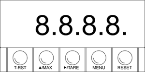
Front
of The Meter

Figure 2-1.
Front-Panel
METER
DISPLAY
| Digital
LED display |
0.9.9.9.
or 9.9.9.9. 4-digit 7ûsegment, 0.56ö high LED display with programmable
decimal point. |
METER MODES |
| Run
Mode |
The
meter is in the run mode when the display is actively showing a
process. |
| Configuration
Mode |
The
meter is in the configuration mode when you press the MENU button
to enable meter configurations. |
METER
BUTTONS
T-RST button - Clears the tare value.
 /MAX
button /MAX
button
In the run mode, press the  MAX
button to show the maximum value if jumper S3 is installed: the meter
momentarily shows " ", then flashes the maximum value encountered
since the last peak reset. Press the MAX
button to show the maximum value if jumper S3 is installed: the meter
momentarily shows " ", then flashes the maximum value encountered
since the last peak reset. Press the  MAX
button to show the VALLEY value if jumper S3 is removed: the meter
momentarily shows ô0000ö then flashes the minimum value encountered since
the last valley reset. In the configuration mode, press the MAX
button to show the VALLEY value if jumper S3 is removed: the meter
momentarily shows ô0000ö then flashes the minimum value encountered since
the last valley reset. In the configuration mode, press the  MAX
button to change the flashing digit's value (increments by one). MAX
button to change the flashing digit's value (increments by one).
 /TARE
button /TARE
button
In the run mode, press the  /TARE
button to tare the display value to zero. In the configuration mode, press
the /TARE
button to tare the display value to zero. In the configuration mode, press
the  /TARE button
to scroll through available choices, or to move one digit to the right. /TARE button
to scroll through available choices, or to move one digit to the right.
MENU Button
In the run mode, press the MENU button to enable meter configuration changes.
Refer to specific procedure for more details.
RESET Button
In
the run mode, press the RESET button to reset the Peak and Valley
registers: the meter momentarily shows "PrSt" or "VrSt"
, then resets both values. In the configuration mode, press the RESET
button twice quickly to escape from the configuration mode.
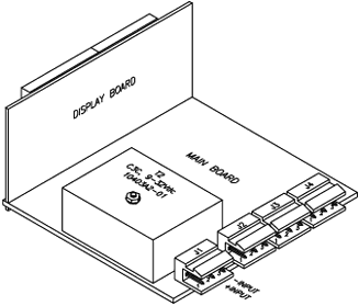
BACK
OF THE METER
Figure 2-2
shows the connectors on the back of the meter. Table 2-2 gives a brief
description of each connector at the back of the meter. Refer to Figure
2-3 for dc-power connection information.


Figure 2-2. Connectors for AC-Power (Top)
and DC-Power (Bottom)
|
Connector
|
Description
|
|
J1-1
J1-2
J1-3
|
AC line connection (No Connection on dc-powered units).
AC neutral connection (+ input on dc-powered units).
AC earth ground (dc-power return on dc-powered units). |
|
J2-1
J2-2
J2-3
|
Remote tare connection with momentary switch to J2-2.
J2-2 Digital Return (RTN).
Tare reset with momentary switch to J2-2. |
|
J3-1
J3-2
J3-3
|
Hold input (active low) - Connect to J2-2 to hold meter reading
(does not update Min/Max).
+EXC: Positive excitation connection from meter (10, 24 Vdc).
-EXC: Negative excitation connection from meter (10, 24 Vdc). |
|
J4-1
J4-2
J4-3
|
Analog Input return (RTN).
Analog Current input (4-20 mA).
Analog Voltage input (0-5 V, 0-10 V etc.). |

Figure 2-3.
DC-Power Connections
DISASSEMBLY
You may need to open up the meter for one of the following reasons:
* To check or change the 115 or 230 Vac power jumpers.
* To install or remove calibration jumper on the main board.
Disconnect the power
supply before proceedings.
To remove and access the main board, follow these steps:
1. Disconnect the main power from the meter.
2. Remove the front lens.
3. Pull the meter forward, out of its case.
|
 TOC
TOC
 Back
Back
 Next
Next